Sales
Rental
Repair
Unistrut, Pipe Hangers & Caddy
519
Boise, ID 208-377-0158
Eugene, OR 541-342-3641
Idaho Falls, ID 208-522-7082
Medford, OR 541-779-0187
ANVIL
Beam Clamps
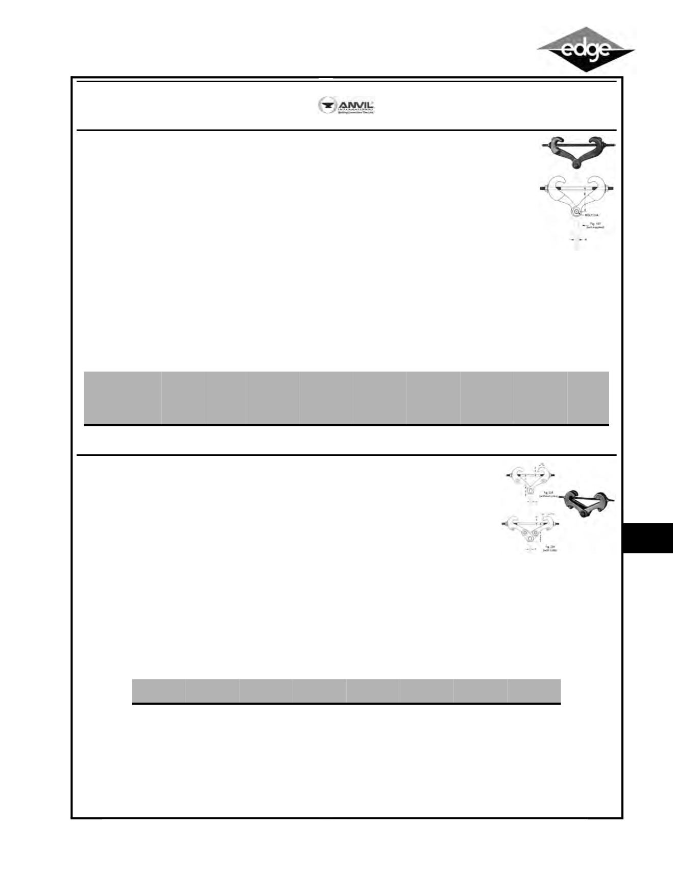
Figure 218 Malleable Beam Clamp Without Extension Piece
•
Material: Malleable iron jaw, steel tie rod, nuts and washer
•
Finish: Plain or Galvanized
•
Recommended for attachment to structural steel
•
Use in conjunction with beams where beam widths are from 2-3⁄8" minimum to 7" maximum and flange thickness does
not exceed 0.60"
•
Complies with Federal Specification A-A-1192A (Type 30)
WW-H-171-E (Type 30), ANSI/MSS SP-69 and MSS SP-58 (Type 30)
•
UL, ULC Listed (Sizes 3⁄4" - 12" pipe size, when used with the Fig. 157 extension piece 3/8" -7⁄8" rod sizes)
•
FM Approved (Sizes 3⁄4" - 4” pipe size, when used with the Fig. 157 extension piece 3⁄8" rod size)
•
Installation: The malleable beam clamp Fig. 218 may be used with an eye rod, or Fig. 157 extension piece
•
Features: Functional design insures proper fit for all beam sizes
•
Tie rod locks clamp in place when nuts are tightened
•
Ordering and stocking simplified because of one universal size
•
Design allows hanger rod to swing from vertical providing
flexibility at the beam clamp
•
Specify figure number, name and finish
•
Note: When used with Fig. 157 extension piece, an
additional inch or more of vertical adjustment is obtained
ANVIL
Beam Clamps
Figure 228 Universal Forged Beam Clamp W/ Upper Nut Right Hand Thread
•
Material: Forged steel
•
Finish: Plain or Galvanized
•
For suspension of heavy loads from beams with flange widths to 15" and flange thickness to 1.031
•
Complies with Federal Specification A-A-1192A (Type 28 without links; Type 29 with links), WW-H-171-E
(Type 30 & 31), ANSI/MSS SP-69 and MSS SP-58 (Type 28 without links; Type 29 with links)
•
Installation: Fit jaws over edges of lower beam flange and tighten nuts on tie rod to lock
clamp in place
•
Features: Upper nut is tapped to any specified size up to the maximum rod size
•
Specify clamp size, figure number, name, rod size and finish
•
Note: The application of a load to a structural beam by means of a beam clamp produces a transverse stress, perpendicular to the axis of the
beam, in the flange to which the load is applied. Size per load, beam flange width and rod size
•
Contact Edge for Rod Takeout Specs for different beam widths
•
Clamp sizes 3 and 5 furnished with links
Item #
Max Rod
Size A
(in.)
Max Load
(lbs.)
Weight
(lbs.)
Rod Take
Out (in.)
Beam
Flange
Width 2-3/8”
Rod Take
Out (in.)
Beam
Flange
Width 3”
Rod Take
Out (in.)
Beam
Flange
Width 4”
Rod Take
Out (in.)
Beam
Flange
Width 5”
Rod Take
Out (in.)
Beam
Flange
Width 6”
Rod Take
Out (in.)
Beam
Flange
Width 7”
Bolt Dia.
(in.)
AV218
⁷⁄₈
1,365
2.2
3
¹⁄₂
3
⁷⁄₁₆
3
⁵⁄₁₆
2
¹⁵⁄₁₆
2
⁹⁄₁₆
1
⁷⁄₈
⁷⁄₁₆
Item #
Clamp Size
No.
Max Rod
Size A (in.)
Max Load
(lbs.)
Weight
(lbs.)
Z Max (in.)
B (in.)
Jaw & Nut
Size
AV228-1
1
⁵⁄₈
2,160
3.3
0.60
1
¹⁄₁₆
228-1
AV228-2
2
⁷⁄₈
4,480
7.0
0.60
1
³⁄₈
228-2
AV228-3
3
⁷⁄₈
4,480
10.6
0.60
1
³⁄₈
228-2
AV228-4
4
1
¹⁄₂
11,500
19.3
1.031
2
³⁄₈
228-3
AV228-5
5
1
¹⁄₂
11,500
31.0
1.031
2
³⁄₈
228-3


